

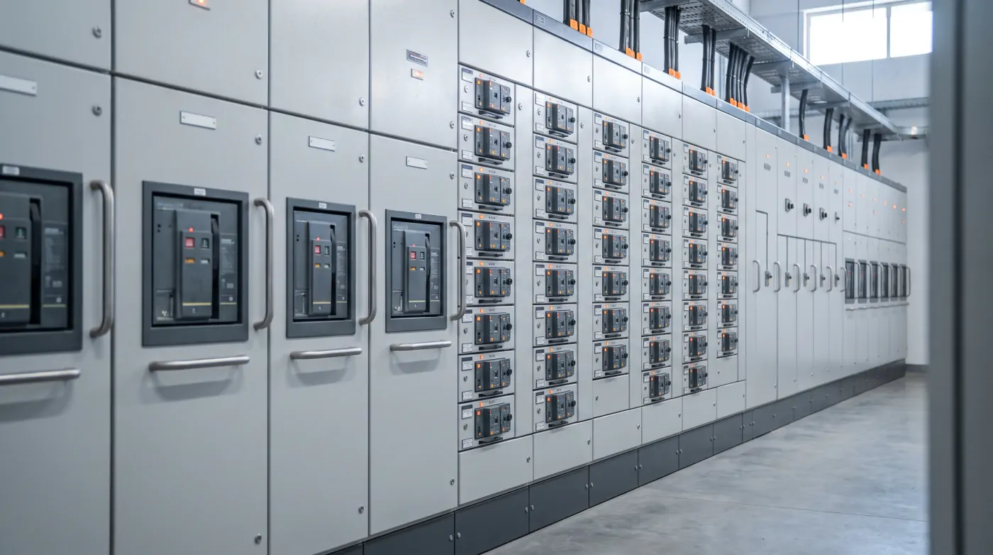
PCC and MCC are the two LT panels every plant has — and the two most often confused in tenders and purchase orders. Both are low-voltage switchgear assemblies, both are built from the same sheet steel and busbars, and they often stand side by side in the same electrical room. But they do very different jobs.
The Short Answer
- A Power Control Centre (PCC) receives power from the transformer or DG set and distributes it to the plant's main loads and sub-panels.
- A Motor Control Centre (MCC) receives power from the PCC and starts, stops, protects and controls motors.
In a typical plant the power flow is: Transformer → PCC → MCCs, PDBs and large loads → Motors and equipment.
What Goes Inside a PCC
A PCC is built around high-current incomers and outgoing feeders:
- Incomers — Air Circuit Breakers (ACBs), typically 800 A to 4000 A or more, from the transformer and DG set. Mechanical or electrical interlocks prevent paralleling sources that should not be paralleled.
- Bus coupler — to split or join bus sections.
- Outgoing feeders — MCCBs or ACBs feeding MCCs, power distribution boards, capacitor panels, compressors and other large loads.
- Metering and protection — multifunction meters, protection relays (overcurrent, earth fault, under/over voltage), and often an energy monitoring system.
- Main busbars — copper or aluminium, sized for the transformer's full-load current and the system's short-circuit level.
An APFC (automatic power factor correction) panel is often connected to, or built into, the PCC.
What Goes Inside an MCC
An MCC is a row of motor feeders, each with its own starter:
- Feeder protection — MCCB or MPCB (motor protection circuit breaker).
- Starter — DOL, star-delta, soft starter or VFD depending on motor size and duty.
- Contactors and overload relays, or electronic motor protection relays.
- Control circuit — start/stop push buttons, indication lamps, local/remote selector, interlocks.
- Interface to the PLC — auxiliary contacts and signals for running, tripped and remote control.
When the MCC is controlled by a PLC with intelligent motor protection relays and fieldbus communication, it is often called an IMCC (Intelligent MCC).
Key Differences at a Glance
| PCC | MCC | |
|---|---|---|
| Main job | Power distribution | Motor control and protection |
| Fed from | Transformer / DG set | PCC |
| Main devices | ACBs, MCCBs, bus couplers | MCCBs/MPCBs, contactors, starters, VFDs |
| Typical incomer | 800 A – 4000 A+ | 100 A – 1600 A |
| Feeders | Few, high-current | Many, motor-rated |
| Control wiring | Limited | Extensive (starters, interlocks, PLC I/O) |
Form of Separation and Type Testing
Both panels should be built to IEC 61439 (adopted in India as IS/IEC 61439), which defines verification of temperature rise, short-circuit withstand and dielectric properties. Specify the form of internal separation — Form 1 up to Form 4b — which decides how far busbars, functional units and terminals are segregated. Higher forms allow maintenance on one feeder while neighbouring feeders stay live, at a higher cost.
What to Include in Your Specification
- Source and ratings — transformer kVA, fault level (kA for 1 second), DG set rating.
- Busbar — material, current rating, and short-circuit withstand rating.
- Feeder list — each feeder's load, rating, starter type and protection.
- Form of separation and IP rating — for example Form 3b, IP54 for an indoor electrical room.
- Preferred switchgear makes — Schneider, Siemens, ABB, L&T, etc.
- Sheet steel — CRCA thickness for frame and doors, and powder-coat shade (RAL 7035 is common).
- Cable entry — top or bottom, gland plates, and cable alley width.
- Metering, communication and PLC interface requirements.
- Testing — routine tests, factory acceptance test (FAT) and the documents you expect: GA drawings, single-line diagram, wiring diagrams and test reports.
Common Mistakes
- Sizing busbars on running current but not on the system's short-circuit level.
- Leaving no spare feeders — plan 10–20% spare space for future loads.
- Ignoring heat: VFD-heavy MCCs need ventilation fans or panel air conditioning.
- Mixing PCC and MCC duties in one panel to save cost, which makes maintenance and fault isolation harder.
Kamakshi designs, manufactures and tests PCC, MCC, IMCC, APFC, AMF and PLC panels in Ahmedabad, and supports installation and commissioning on site. Send us your single-line diagram for a feeder-by-feeder review.
Further Reading
- MCC Panel Specification Guide
- APFC Panel Benefits for Industrial Plants
- Control Panel Manufacturing Checklist
Related Articles
Explore more technical guides from our automation knowledge base.