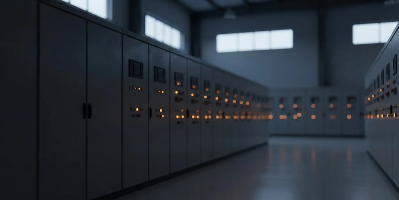

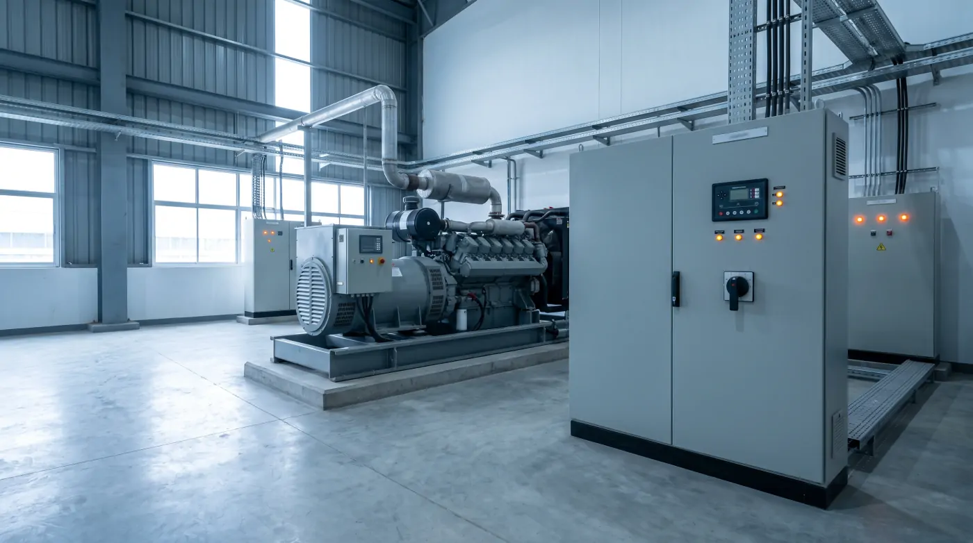
What Is an AMF Panel?
An Auto Mains Failure (AMF) panel is an electrical control panel that automatically starts a diesel generator set when utility power fails, transfers the load to the generator, and then returns the load to utility power when it is restored — all without manual intervention. In Indian industrial and commercial facilities where grid power interruptions are frequent, AMF panels are essential for maintaining production continuity, protecting sensitive equipment from unplanned shutdowns, and eliminating the need for an operator to manually manage the changeover.
An AMF panel is typically installed between the utility incomer and the DG set output, with a transfer switch (either mechanical changeover or contactor-based scheme with electrical interlocks) controlling which source feeds the load.
Key Components of an AMF Panel
A standard AMF panel contains the following components:
Voltage sensing relay (VSR): Monitors the three-phase utility supply continuously. When any phase voltage falls below the set threshold (typically 80–85% of nominal, i.e., below ~340 V on a 415 V system) for the configured time delay (0–10 seconds adjustable), it signals mains failure.
AMF controller: The intelligence of the panel. Modern AMF controllers (ComAp, Deepsea Electronics, Kirloskar-compatible units) are microprocessor-based and handle start/stop sequencing, transfer timing, alarm management, and data logging. Earlier panels used discrete relay logic.
DG start relay and crank timers: Sends the start signal to the DG set's engine control unit. Includes crank time (typically 10–15 seconds), rest time between crank attempts, and maximum attempts before lockout alarm.
Changeover switch / interlocked contactors: Ensures mains and DG source are never paralleled. A double-throw mechanical changeover switch provides positive physical isolation. Contactor-based schemes use auxiliary contacts to enforce interlock — the mains contactor cannot close if the DG contactor is closed and vice versa. For critical loads, a motorised changeover switch with padlock provision is preferred.
Voltage and frequency monitoring relay: Verifies the DG set has reached stable voltage (±10% of nominal) and frequency (47.5–52 Hz) before initiating the transfer. Transferring load before the generator is stable causes voltage dips and frequency excursions that can damage sensitive equipment.
Generator protection relay: Protects the DG set from overload, short circuit, reverse power, and earth fault. Minimum protection includes overcurrent (IDMT) and earth fault relays per IS 4722.
How the AMF Control Logic Works
The AMF sequence unfolds in defined steps:
Mains monitoring: VSR continuously monitors utility phases. In healthy state, mains contactor is closed, DG is in standby (engine off).
Mains failure detection: All three phases healthy for stable operation. On voltage or frequency excursion beyond limits for the configured delay, mains failure is declared.
DG start sequence: AMF controller signals DG to start. Crank signal is sent for up to 3 attempts of 10–15 seconds each, with 10-second rest intervals. Glow plug preheat (for cold climates or after long idle) may precede cranking.
Stable voltage check: Once engine fires and generator output reaches rated voltage and frequency, a warm-up delay of 10–30 seconds runs to allow oil pressure and temperature to stabilise.
Load transfer: Mains contactor opens (with 100–200 ms delay). Transfer switch moves to DG position. DG contactor closes. Load is now fed from generator.
Mains restoration monitoring: AMF controller continues monitoring utility supply. Once utility voltage and frequency have been within limits for a configurable period (typically 30–180 seconds to avoid chasing unstable mains), mains restoration is declared.
Transfer back to mains: DG contactor opens. After brief dead-transfer period (50–100 ms), mains contactor closes. Load returns to utility.
DG cool-down: Engine runs off-load for 3–5 minutes to allow exhaust manifold and turbocharger to cool before shutdown signal is issued.
AMF Panel Wiring and Control Connections
The AMF panel interfaces with both the utility distribution board and the DG set. Key wiring connections:
- Utility sensing: 3-phase voltage sensing from incomer side of changeover, typically through control fuses or a control transformer for isolated sensing
- DG output sensing: 3-phase voltage from DG alternator output terminals
- DG start circuit: Normally open contact to DG start solenoid (typically 12 V or 24 V DC, verified with DG set manufacturer)
- DG run feedback: Normally open oil pressure switch or alternator excitation signal confirming engine running
- Remote alarm outputs: Potential-free contacts for mains fail alarm, DG fail alarm, and panel fault to BMS or plant SCADA
All control wiring in the AMF panel should be a minimum 1.5 mm² flexible copper, correctly labelled and numbered at both ends to match the wiring diagram. Control fuses should be individual 2A HRC fuses per circuit.
Commissioning Steps
Commissioning an AMF panel requires a systematic approach to test each part of the sequence safely:
Pre-commissioning checks: Verify all wiring matches the approved drawing. Check insulation resistance of panel wiring (500 V Megger, minimum 10 MΩ). Verify DG set is mechanically ready with oil, coolant, and fuel.
Manual DG start test: Before enabling AMF logic, start the DG manually from the panel and verify it reaches rated voltage and frequency. Check phase rotation with a phase sequence indicator — it must match utility phase rotation.
Manual changeover test: With DG running and load small (say, lighting circuits only), manually operate the changeover switch and verify load transfers without issue.
AMF simulation test: With small test load connected, simulate mains failure by opening the utility incomer. Time the sequence: detection delay → DG start → transfer. Verify it matches the design specification. Record actual times in the commissioning record.
Mains restoration test: Restore utility supply and verify auto-retransfer and DG cool-down sequence work correctly.
Protection relay tests: Inject test current/voltage to verify protection relay operation and correct trip circuit continuity.
Maintenance Schedule
AMF panels require periodic maintenance to remain reliable:
- Monthly: Check DG fuel level, battery electrolyte, and run DG on load test for 30 minutes
- Quarterly: Check all relay settings, clean panel interior, inspect terminals for looseness and corrosion
- Annually: Test all protection relay trip functions, replace panel battery if voltage below specification, perform full AMF sequence test with actual mains failure simulation
Further Reading
Related Articles
Explore more technical guides from our automation knowledge base.