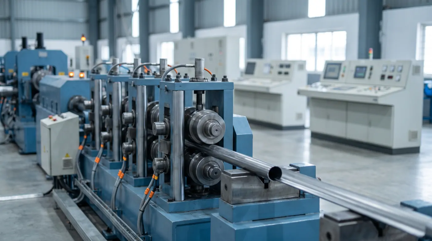
An ERW (electric resistance welded) tube mill turns flat steel strip into round, square or rectangular tube in one continuous line. Mechanically, it is a long train of roll stands. Electrically, it is a set of tightly synchronised drives under PLC control — and the quality of that electrical system decides how fast the mill can run, how much scrap it makes and how quickly it can change sizes.
The Line, Section by Section
- Uncoiler — holds the steel coil; double-mandrel uncoilers allow the next coil to be loaded while one runs.
- Pinch roll and leveller — flattens the coil ends for joining.
- Strip joiner (shear and welder) — joins the tail of one coil to the head of the next so the mill never stops for a coil change.
- Accumulator — stores strip so the mill keeps running while the entry end stops for joining. Horizontal spiral accumulators are common on high-speed lines.
- Forming mill — breakdown and fin-pass stands gradually bend the strip into an open tube.
- Welding section — the edges are heated by a high-frequency (HF) induction welder and squeezed together; the outside weld bead is scarfed off.
- Cooling section — the tube is cooled before sizing.
- Sizing and shaping mill — brings the tube to final diameter, or forms square and rectangular sections; a Turks head straightens it.
- Flying cut-off saw — cuts the moving tube to length.
- Run-out conveyor and collection — tubes are kicked off into bundles, with rejects separated.
Drives and Synchronisation
The forming, fin-pass and sizing sections are driven by large AC motors on VFDs (older mills often use DC drives). Their speeds must be matched to each other, and to the welding speed, so the strip is neither pushed nor pulled between sections. The PLC sends a common line-speed reference to all drives, with a trim for each section.
The accumulator has its own drives: an entry pinch roll that fills it at high speed and a turntable or exit drive that feeds the mill. The PLC manages fill level so that the accumulator never runs empty during a coil change.
The Flying Cut-Off
The cut-off saw must travel with the tube at exactly line speed, cut, and return — many times a minute. This is a motion control job: an AC servo drive on the saw carriage, controlled by a motion controller or PLC motion function, using an encoder-driven length measuring wheel on the tube. Length accuracy and saw blade life both depend on how well the carriage tracks the tube during the cut. Cold saws give clean, burr-free cuts at higher cost; friction saws are simpler but leave more burr.
PLC, HMI and Networks
A modern tube mill typically uses one main PLC with distributed I/O and drives connected on an industrial Ethernet network such as PROFINET. Separate control desks — at the uncoiler, joiner, accumulator, main mill and cut-off — each carry an HMI or push-button station. The HMI shows line speed, accumulator level, weld power, cut length and alarms, and stores recipes for each tube size.
Safety Systems
- Emergency stop circuits along the full line length, with safety relays or a safety PLC.
- Guarding and interlocks on the accumulator, saw and roll stands.
- Interlocks preventing welder power-on unless the mill is running and coolant is flowing.
- Lock-out points for roll changes.
Buying or Upgrading — What to Check
- Drive and PLC makes and whether spares and support are available locally.
- Complete electrical documentation — single-line diagram, wiring diagrams, cable schedule, I/O list and drive parameter backups.
- PLC program access — find out whether the program is supplied open or locked, and what support is offered if it is locked.
- Power requirement — the connected load decides your transformer and PCC sizing; plan this early.
- Harmonics and power factor — many drives plus an HF welder affect power quality; budget for filters and APFC.
- Commissioning support — insist on running real coils of each size during acceptance.
Common Problems We See
- Accumulator running empty during joins because of wrong fill-speed settings.
- Cut-length variation from a slipping or dirty measuring wheel.
- Section speed mismatch after a drive replacement because parameters were not restored.
- Nuisance trips from poorly earthed encoder cables next to motor cables.
Kamakshi provides PLC programming, VFD setup and commissioning, panel manufacturing and installation and commissioning for tube mills and steel processing lines across India.
Further Reading
- Rolling Mill Automation for TMT Bar Plants
- VFD Fault Codes Explained
- PLC Troubleshooting: Common Errors
Related Articles
Explore more technical guides from our automation knowledge base.