

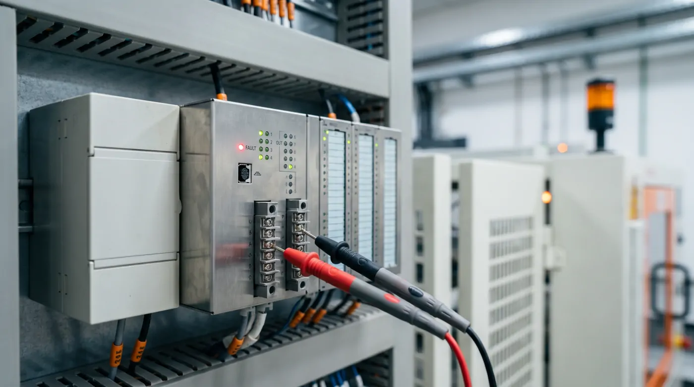
Introduction to PLC Fault Diagnosis
A PLC fault in a production environment can stop the line and cost thousands of rupees per hour in lost output. The difference between a 15-minute recovery and a 4-hour shutdown usually comes down to how systematically the maintenance engineer approaches the diagnosis. This guide covers the ten most common PLC errors encountered in Indian industrial plants — across Siemens, Allen-Bradley, Mitsubishi, and Delta platforms — with practical steps to identify and fix each one.
Before starting any PLC troubleshooting, always check the basic electrical supply: confirm 24 V DC power supply output is within ±10%, check all fuses in the control cabinet, and verify the PLC CPU status LED. Most PLCs use a combination of RUN (green), STOP (yellow), and FAULT/ERROR (red) LEDs to indicate system state.
Error 1: Digital Input Not Reading Correctly
Symptom: A field sensor is active but the PLC input address shows 0 in the monitoring screen.
Causes: Blown fuse on the input card, failed sensor, wiring break, incorrect input voltage level, or input card failure.
Fix: Use a multimeter to measure voltage at the input terminal. For a sinking (NPN) input card, you should measure 24 V between the input terminal and the common (0 V). For a sourcing (PNP) input card, measure 24 V between common (24 V) and the input terminal. If voltage is correct at the terminal but the input is still not registering, suspect the input card — swap with a spare if available. If voltage is absent, trace back to the sensor and field wiring.
Error 2: Digital Output Not Switching the Field Device
Symptom: The output coil is energised in the PLC logic but the field device (motor contactor, solenoid valve) does not operate.
Causes: Blown output fuse, failed output transistor or relay, incorrect wiring, or insufficient load current.
Fix: With the output forced ON in the PLC (use force/override cautiously and document), measure voltage at the output terminal. Transistor outputs (DC) should show load supply voltage. Relay outputs should show continuity across the output relay contacts. If the output measures correct voltage but the field device still does not operate, the fault is in the field wiring or the device itself. Check the contactor coil for continuity — coil resistance should typically be 100–500 Ω for 24 V coils.
Error 3: Communication Fault on Modbus RTU Network
Symptom: PLC shows communication error bits set, SCADA or HMI shows offline status for remote I/O or drive.
Causes: Incorrect baud rate or parity settings, missing or incorrect termination resistors, shielding problems, or address conflict.
Fix: Verify that all devices on the Modbus RTU network have the same baud rate and parity settings — mismatches are the most common cause. Confirm the RS-485 network has 120 Ω termination resistors at both physical ends of the cable only (not at intermediate nodes). Check that cable shielding is grounded at one end only (typically the PLC end) to avoid ground loops. Use a Modbus analyser or the PLC's built-in diagnostic buffer to capture raw frames and identify which device is failing to respond.
Error 4: Scan Time Overrun / Watchdog Fault
Symptom: PLC CPU faults with a watchdog timer error and goes to STOP mode.
Causes: Program loop without exit condition, excessive interrupt load, too many communication requests per scan, or complex mathematical processing in the main scan.
Fix: Check the scan time history in the CPU diagnostic buffer. Identify which routine or function block is consuming excessive scan time. Move heavy processing (complex calculations, large data sorting) to a lower-priority background task or break it across multiple scans. Review all FOR/WHILE loops to ensure they have a bounded number of iterations. Disable unused communication tasks that are polling on every scan.
Error 5: Analog Input Reading Incorrectly
Symptom: Analog input (4–20 mA pressure transmitter, temperature sensor) shows wrong value, stuck at 0, or erratic.
Causes: Open circuit (transmitter failure gives 0/3.8 mA), short circuit, incorrect scaling in the PLC program, or power supply issue to the transmitter.
Fix: Measure the current loop with a clamp meter or series ammeter. A healthy 4–20 mA loop should read between 4 mA (zero) and 20 mA (full scale). If the reading is below 3.8 mA, the transmitter or the 24 V loop supply is faulty. If current is correct but PLC value is wrong, recheck the scaling block in the program — verify the engineering unit range matches the transmitter datasheet. For Siemens S7, check the AI channel properties for the correct measurement range (0–20 mA vs 4–20 mA).
Error 6: CPU Memory Error or Corrupt Program
Symptom: PLC fails to go to RUN after power cycle, or program behaves unpredictably after a power interruption.
Causes: Power loss during program write, failed battery backup, EEPROM/flash corruption.
Fix: Most modern PLCs store the program in non-volatile flash memory and do not require a battery for program retention. However, retain data (counters, data registers marked as retentive) is typically stored in battery-backed SRAM. A dead CPU battery causes retentive data loss on power cycle. Check the battery LED (usually separate from fault LED). Replace the lithium backup battery (typically CR2032 or similar, ₹50–150) with the CPU powered ON to avoid data loss during replacement. After replacement, verify retentive data has been restored correctly.
Error 7: HMI Communication Loss
Symptom: HMI screen shows "Connection Lost" or "Server Offline" and operator cannot see real-time values.
Causes: Ethernet cable fault, IP address conflict, incorrect PLC port configuration, or HMI driver mismatch after PLC firmware update.
Fix: Ping the PLC IP address from a laptop connected to the same network segment. If ping fails, check the Ethernet cable and switch port — use a cable tester to rule out physical layer issues. If ping succeeds but HMI still cannot connect, verify the port number configured in the HMI driver matches the PLC configuration (S7-1200 uses port 102 for S7 protocol, port 502 for Modbus TCP). After PLC firmware updates, the HMI driver may need to be updated to match — check the manufacturer compatibility matrix.
Error 8: Motor Not Starting from PLC (Logic Issue)
Symptom: Operator presses start from HMI, output does not energise, but no fault is showing.
Causes: Interlock condition not met, permissive input missing, run enable bit not set by program, or mode selector in wrong position.
Fix: Use the PLC's online monitoring to trace the rung controlling the motor output. In ladder logic, follow the logic from left to right — identify which contact is open (grey/hollow) that is blocking the output from energising. Common culprits: E-stop not reset (check E-stop loop continuity), thermal overload trip not reset (check overload relay and its feedback contact), safety relay not in ready state, or mode selector (local/remote) in wrong position. Document all interlock conditions and create a checklist for shift handover.
Error 9: Counter or Timer Preset Not Maintained After Power Cycle
Symptom: Production counters reset to zero every time power is cycled, losing shift totals.
Causes: Counter/timer data registers are not configured as retentive in the PLC memory settings.
Fix: In the PLC configuration (hardware configuration or data block settings), mark the relevant data registers or function block instances as retentive. For Siemens S7-1200/1500, configure the data block as "Optimized" or "Classic" and enable the "Retain" property for specific variables. For Allen-Bradley, use the program file memory configuration. Test by writing a value, cycling power, and confirming the value is preserved.
Error 10: Intermittent Faults That Cannot Be Reproduced
Symptom: Machine stops occasionally with a vague fault, but when engineers investigate, the system appears healthy.
Causes: Electrical noise on input wiring, vibration-induced loose connections, thermal expansion causing intermittent contact, or marginal sensor signal.
Fix: Enable the PLC's diagnostic buffer logging and configure it to capture all transitions with timestamps. Review the buffer after the next fault occurrence. Install a 24 V signal conditioner or filter on suspect inputs. Check all terminal screws in the panel — in Indian industrial environments with vibration from heavy machinery, terminal screws loosen over time. Use a thermal camera during operation to identify hot terminations indicating high resistance joints.
Building a Troubleshooting Culture
The most effective plants maintain a fault log in a simple notebook or spreadsheet next to the panel. Each fault entry records: date, time, fault description, cause found, corrective action, and time to repair. Over 6–12 months, this log reveals patterns — recurring faults on the same module, seasonal correlation with monsoon humidity, or gradual degradation trends — that guide preventive maintenance decisions.
Further Reading
Related Articles
Explore more technical guides from our automation knowledge base.