

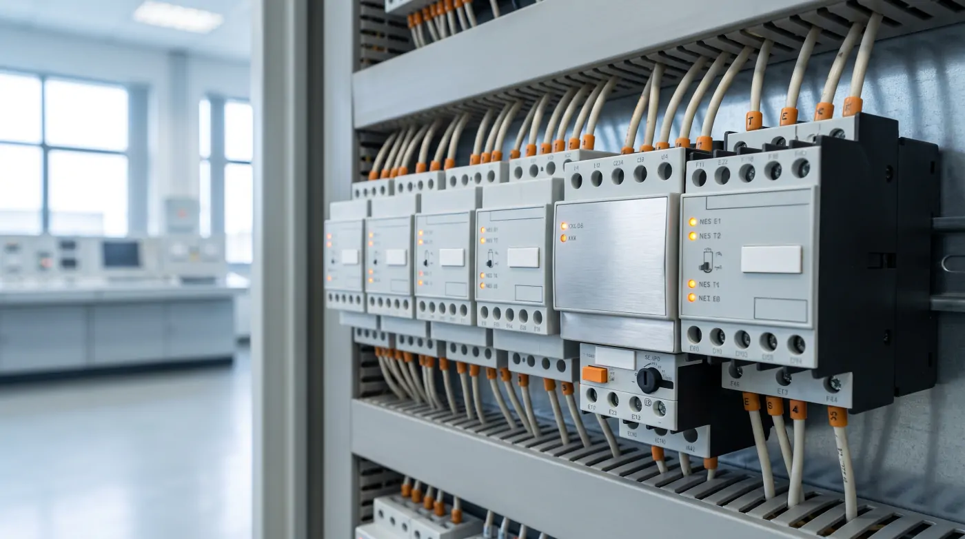
Why Motor Protection Matters
AC induction motors are the workhorses of Indian industry — drives ranging from 0.37 kW fractional-horsepower units on small conveyors to 2000 kW units on large centrifugal pumps and compressors all rely on adequate electrical protection to deliver reliable service life. Without proper protection, a motor exposed to sustained overloading, phase loss, or locked rotor conditions will suffer insulation failure, winding burnout, and mechanical damage that can cost ₹30,000 to ₹10,00,000 to repair or replace depending on the size.
Motor protection has evolved from simple bimetal thermal relays to sophisticated multifunction electronic relays with communication interfaces. Understanding the types available and when to use each is essential for specifying an appropriate protection package for your application.
Thermal Overload Relay (Bimetal Type)
The bimetal thermal overload relay is the most widely used motor protection device in Indian industrial panels. It works by passing motor current through a set of bimetal strips that bend when heated by excessive current. When the deflection exceeds the calibrated threshold, the bimetal trips a set of contacts that open the motor contactor circuit.
Advantages:
- Very low cost (₹300–₹1,500 for relays up to 32 A range)
- Simple, no external power supply required
- Inherits a crude memory effect — if the motor trips on overload and is reset immediately and restarted, the partially heated bimetal trips faster on the second occurrence, providing protection against repeated hot restarts
- Widely available across India from ABB, Schneider, Siemens, L&T, and Havells
Limitations:
- Does not detect phase loss unless specifically designed for it (some single-phase sensitive versions are available)
- Cannot distinguish between motor current and ambient temperature effects accurately in variable temperature environments
- Trip class (10, 20, 30) is fixed at purchase — cannot be adjusted in service
- No fault logging or communication output
- Accuracy affected by ambient temperature — derate or use with ambient compensation if panel temperatures exceed 50°C (common in Indian summer conditions)
When to use: For standard motors below 30 kW in non-critical applications where digital protection is not justified.
Electronic Overload Relay
Electronic overload relays replace the bimetal element with a microprocessor-based measurement system using current transformers (built-in or external). They measure true RMS current on all three phases separately and calculate thermal memory based on the motor's thermal model.
Key features over thermal relays:
- Phase loss protection: Detects loss of any single phase within 1–3 seconds, a major cause of motor burnout in India where phase failures are common
- Phase unbalance protection: Trips when current imbalance exceeds a threshold (typically 20–40%), protecting against open-phase in the supply or motor winding asymmetry
- Adjustable trip class: Select Class 10 for normal start, Class 20 for high-inertia loads, Class 30 for very high inertia (centrifuge, large fan)
- Ground fault indication (on some models)
- Remote reset and status outputs: Potential-free contacts for trip, warning, and status feedback to PLC or DCS
- Temperature input: Some models accept PTC thermistor input directly from motor winding temperature sensors
Examples: ABB EF (Earth Fault) series, Siemens 3RB20, Schneider LT9, Mitsubishi TH-N series.
Cost: ₹2,000–₹15,000 for relays covering motor ranges up to 100 A.
When to use: For all motors above 15 kW, three-phase motors in critical processes, and any motor where phase loss or unbalance is a concern.
Dedicated Motor Protection Relay (Multifunction)
For motors above 45–75 kW, or in critical process applications where motor failure causes significant production loss or safety risk, a dedicated multifunction motor protection relay provides comprehensive protection in a single device.
Typical protection functions in a multifunction motor relay (per IEC 60255 and ANSI device numbering):
| Protection | ANSI Code | Description |
|---|---|---|
| Thermal overload | 49 | Full thermal model with heating and cooling time constants |
| Phase overcurrent | 51 | IDMT or definite time overcurrent, independent per phase |
| Earth fault | 50N / 51N | Sensitive earth fault detection via core balance CT |
| Undercurrent / loss of load | 37 | Detects broken shaft, lost pumping load, pump cavitation |
| Phase unbalance | 46 | Negative sequence current detection |
| Locked rotor | 48 | Stall protection during start and running |
| Starts per hour / restart inhibit | 66 | Limits number of starts to protect windings |
| Thermistor input | 38 | Direct PTC/NTC thermistor input for winding temperature |
| Undervoltage | 27 | Trips on supply voltage collapse |
| Differential (large motors) | 87M | High-speed internal fault protection for motors >1 MW |
Examples: Schneider Tesys T, ABB M102-M, Siemens SIMOCODE Pro, Eaton XTOE series, GE Multilin 369.
Cost: ₹15,000–₹1,50,000 depending on model and features.
Most multifunction relays include Modbus RTU or Profibus communication, allowing motor operating data (current, voltage, temperature, starts, running hours, fault history) to be read by SCADA or PLC — valuable for predictive maintenance programs.
Protection Relay Selection Criteria
When selecting a motor protection relay, evaluate the following:
1. Motor rated current (FLC): The relay must cover the motor's full load current within its adjustment range. Specify the next relay range above the motor FLC.
2. Starting current and time: High-inertia loads (fans, centrifuges) draw starting current for longer than the relay's default Class 10 timing. Use Class 20 or 30, or a relay with adjustable starting inhibit time.
3. Number of starts per hour: Ball mill motors, compressors, and fire pumps may require frequent restart capability. Specify a relay with starts-per-hour limitation and thermal memory reset for emergency override.
4. Environment: In hot panel rooms (>45°C ambient), derate thermal relays or specify ambient-compensated electronic relays. In dusty environments, verify the relay's IP rating or install it in a sealed enclosure.
5. Communication requirement: If the motor feeder is in a PLC-controlled system or the plant has a SCADA system, specify a relay with Modbus RTU output. The incremental cost is small but the operational visibility gained is significant.
6. Standards compliance: Verify the relay meets IEC 60255 for measurement accuracy and IS 13947 for LV switchgear compatibility. For export projects, ensure UL or CE marking as required.
Coordination with Upstream Protection
Motor protection relays do not operate in isolation — they must coordinate with upstream MCCBs and fuses. The overcurrent relay trip time at maximum fault current must be shorter than the upstream MCCB trip time. Plot time-current curves (TCC) for the complete protection chain from the motor feeder to the main incomer to verify selectivity. Incorrect coordination means a motor fault may trip an upstream breaker, blacking out an entire section of the plant instead of just the faulted motor.