
Variable frequency drives save energy, but every standard VFD also draws distorted, non-sinusoidal current from the supply. In a plant with only a few small drives this rarely matters. In a plant where half the connected load runs on drives — textile mills, pumping stations, plastic processing, steel processing — harmonics can quietly overheat transformers, destroy capacitor banks and trip breakers for no apparent reason.
Why VFDs Create Harmonics
A typical VFD's input stage is a six-pulse diode rectifier feeding a DC bus capacitor. The rectifier only draws current at the peaks of the supply voltage, in short pulses. That pulsed current is mathematically equal to the 50 Hz fundamental plus a series of harmonics — mainly the 5th (250 Hz), 7th (350 Hz), 11th and 13th.
The amount of distortion is described by:
- THDi — total harmonic distortion of current, as a percentage of the fundamental.
- THDv — total harmonic distortion of voltage at the supply point.
An unfiltered six-pulse drive can have a THDi well above 30–40%.
Problems Harmonics Cause
- Transformer and cable heating — harmonic currents add losses, so a transformer can run hot even below its kVA rating.
- Capacitor failures — power factor correction capacitors have low impedance at high frequencies, attract harmonic current and can resonate with the transformer. Bulging or failed APFC capacitors are a classic sign.
- Nuisance tripping — breakers, RCDs and protection relays can mis-operate.
- Neutral overheating — in systems with many single-phase electronic loads, triplen harmonics add in the neutral.
- Interference with instruments, PLC analogue signals and communication networks.
- Penalties or connection conditions from the utility where harmonic limits are enforced.
IEEE 519 Limits in Brief
IEEE 519 is the standard most commonly referenced for harmonic limits at the point of common coupling (PCC) — the point where the plant connects to the utility. For systems up to 1 kV, the 2014 edition sets voltage distortion limits of 5% for individual harmonics and 8% THDv. Current limits are expressed as total demand distortion (TDD) and depend on the ratio of short-circuit current to load current; for weaker supplies (ratio below 20) the TDD limit is 5%.
Check your utility's and state's requirements as well; some Indian DISCOMs and industrial parks specify their own limits in connection agreements.
Mitigation Options
1. Line Reactors or DC Chokes
A 3–5% AC line reactor or a DC link choke on each drive smooths the input current and typically brings THDi down to roughly 30–45%. It is the cheapest first step and also protects the drive against supply transients. Many drives include a DC choke as standard.
2. Detuned APFC Panels
If the plant has power factor correction capacitors, replace standard capacitor steps with detuned steps (capacitors with series reactors, commonly tuned around 189 Hz for 7% detuning). This prevents resonance and protects the capacitors without filtering harmonics on its own.
3. Passive Harmonic Filters
Tuned LC filters, either per drive or for a group of drives, absorb specific harmonics (usually the 5th and 7th) and can bring THDi below roughly 8–10%. They must be designed carefully for the actual load, since they can over-compensate at light load.
4. Multi-Pulse Drives
12-pulse or 18-pulse rectifier arrangements, fed by phase-shifting transformers, cancel the lower harmonics. They are common on large drives.
5. Active Front End (AFE) Drives
AFE drives use an IGBT rectifier instead of diodes and draw nearly sinusoidal current with THDi typically under 5%. They can also regenerate braking energy back to the supply. They cost more but solve the problem at source.
6. Active Harmonic Filters
An active filter connected at the main bus measures harmonic current and injects an equal and opposite current. One unit can clean up harmonics from many drives and also correct power factor. Often the best choice for an existing plant with mixed loads.
How to Start
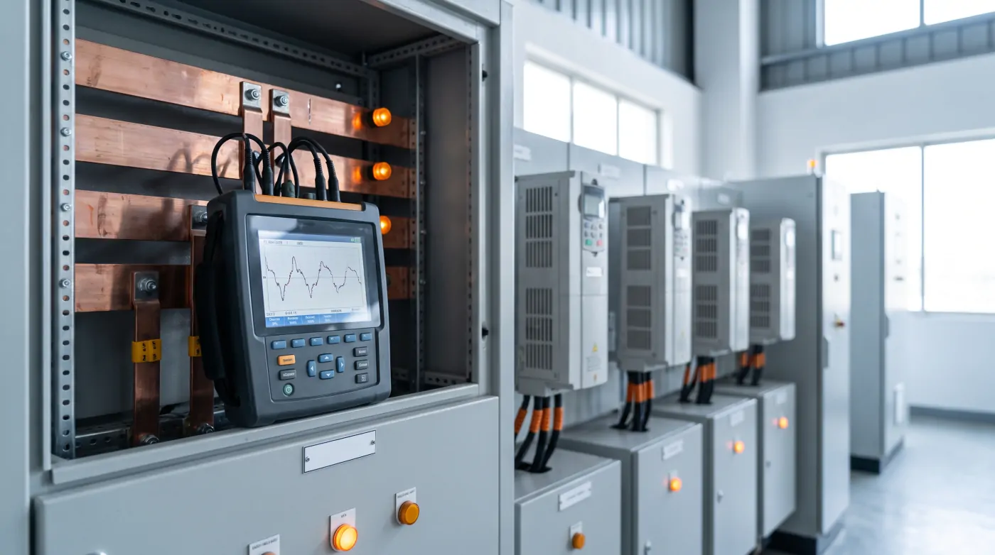
- Measure first — log THDv and THDi at the main incomer and major feeders over a full production cycle with a power quality analyser.
- Check capacitor health in APFC panels.
- Identify the largest harmonic sources — usually the biggest drives.
- Choose mitigation by size — reactors on small drives, detuned APFC, and an active filter or AFE drives where the drive load is large.
Kamakshi carries out power quality and energy audits, builds detuned APFC panels and commissions VFDs with the right input filtering for Gujarat plants.
Further Reading
- APFC Panel Benefits for Industrial Plants
- VFD Energy Saving in Industrial Plants
- Industrial Panel Earthing and Safety
Related Articles
Explore more technical guides from our automation knowledge base.