
Why Earthing Is a Safety-Critical Requirement
Earthing (also called grounding) of industrial control panels is not optional — it is a fundamental safety requirement under Indian Electricity Rules 2005, IS 3043 (Code of Practice for Earthing), and IEC 60364. Proper earthing protects personnel from electric shock, provides a low-impedance fault current path that enables protective devices (MCBs, MCCBs, RCDs) to operate quickly during a fault, and reduces electromagnetic interference (EMI) that can cause malfunction in PLC and instrument circuits.
In Indian factories, inadequate or incorrect earthing is one of the most common causes of both fatal electrical accidents and mysterious control system malfunctions. A panel with poor earthing may pass visual inspection but fail catastrophically during a ground fault. This guide covers the complete earthing and bonding requirements for industrial control panels.
Earth Electrode and Earth Grid Requirements
The earthing system begins at the earth electrode — a conductor buried in the soil to establish a low-resistance connection to the general mass of earth. IS 3043 specifies several electrode types:
- Plate electrode: 600×600 mm copper (3 mm thick) or galvanised iron (6 mm thick) plate buried vertically minimum 3 m below grade
- Pipe electrode: 38 mm GI pipe, 2.5–3 m length, driven vertically
- Strip electrode: 25×3 mm GI strip buried in a trench
For industrial plants, a ring earth electrode surrounding the building perimeter with multiple driven rods at regular intervals is the standard approach. The combined earth resistance of the electrode system should not exceed 1 Ω for large substations, and should be below 5 Ω for general industrial equipment per IS 3043.
Measure earth resistance annually using a three-terminal earth resistance tester (Kyoritsu or equivalent). During monsoon and in hot summer months, resistance varies significantly with soil moisture — conduct measurements in dry season to verify worst-case resistance.
Panel Earthing Bus and Bonding
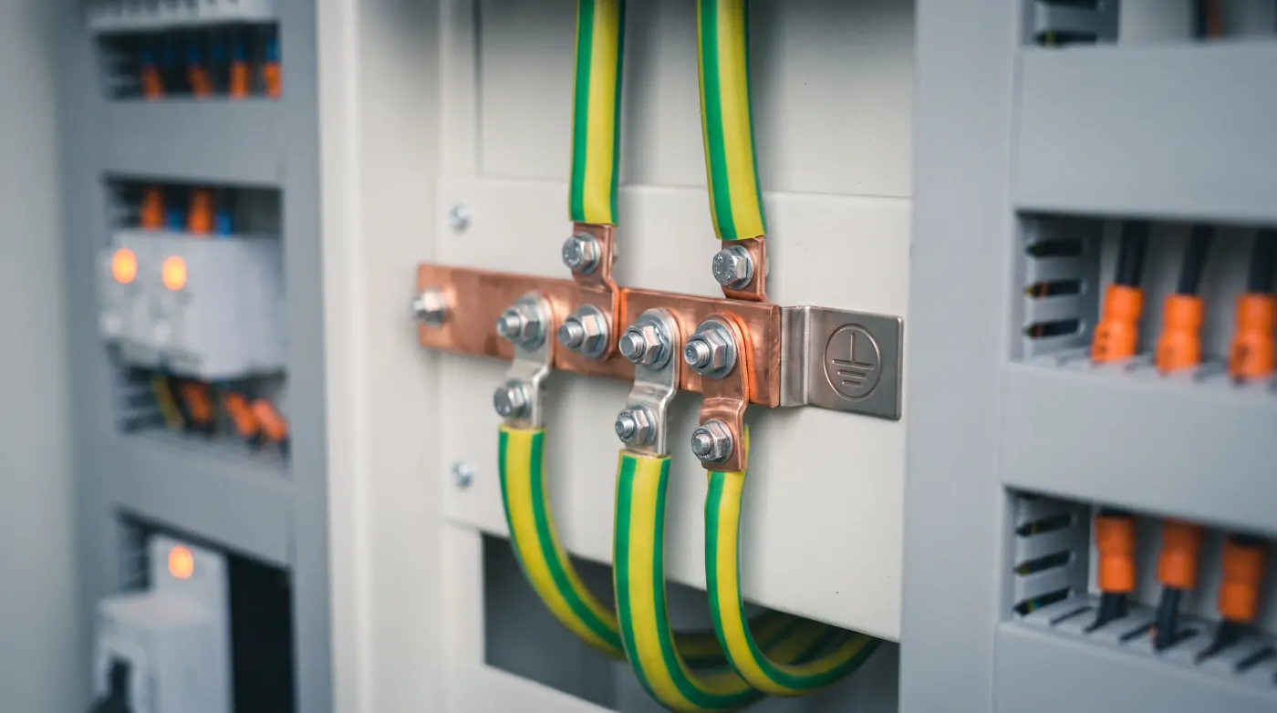
Every control panel must have a dedicated PE (Protective Earth) busbar running the full height of the panel. This busbar should be:
- Minimum 25×3 mm electrolytic copper for panels up to 400 A
- Minimum 40×5 mm copper for larger panels
- Mounted on insulated standoffs (not the same standoffs as the neutral busbar)
- Connected to the plant earth grid with a minimum 16 mm² green/yellow insulated copper conductor (or larger based on fault current calculation per IS 3043 Table 3)
All metallic parts of the panel enclosure — door, back plate, cable gland plate, sub-plate — must be bonded to the PE busbar with minimum 4 mm² green/yellow bonding conductors. Door bonding is particularly important because the door hinges alone do not provide adequate bonding for fault current paths.
Every piece of equipment within the panel that has a protective earth terminal (MCCBs, contactors, drives, PLCs with earth pins) must be individually connected to the PE busbar. Daisy-chaining earth connections from one piece of equipment to the next is not acceptable per IEC 60364-4-41.
Cable Earthing and Gland Requirements
When power cables enter the panel through cable glands, the cable armour (SWA — Steel Wire Armour or AWA — Aluminium Wire Armour) must be terminated to an earth connection at the gland. Brass cable glands with integrated earth tag provide this connection. The earth tag should be connected to the panel PE busbar with a minimum 4 mm² green/yellow conductor.
For screened instrument and control cables, the screen (drain wire or foil/braid) should be earthed at one end only — typically at the control panel end — to prevent circulating currents that cause noise. Double-earthed screens create ground loops that inject 50 Hz noise into sensitive instrument signals, particularly 4–20 mA loops and thermocouple circuits.
Functional Earth vs Protective Earth
A distinction important in industrial control panels is between Protective Earth (PE) and Functional Earth (FE):
- PE provides the fault current return path and personnel protection — this must be connected to the system earth
- FE is a clean reference earth used by electronic equipment (PLCs, drives, instruments) to reduce EMI and provide a stable signal reference — this should be connected via a separate, dedicated conductor to the earth electrode, not shared with the power earth on the PE busbar
In panels containing VFDs or servo drives, high-frequency switching noise flows through the PE connection. If PLC and instrument circuits share the same PE conductor, this noise can cause false triggers, communication errors, and analog signal corruption. The solution is a star-topology earthing arrangement where all earth connections run directly back to a single earth busbar point, minimising shared impedance.
Safety Isolation and Lockout/Tagout (LOTO)
Indian factories are required to implement Lockout/Tagout procedures under the Factories Act 1948 and IS 13947 requirements. Every control panel must have provisions for safe isolation before maintenance:
- Main isolator: Each panel must have an accessible main isolating switch that can be padlocked in the OFF position
- LOTO hasps: The isolator padlock facility should accept multiple padlocks so multiple maintenance personnel can each apply their own lock
- Danger tags: Physical danger tags ("DO NOT ENERGISE — Man at Work") should be applied to all isolation points
- Stored energy: After isolation, wait for VFD DC bus capacitors to discharge (indicated by DC bus voltage LED or discharge timer — typically 5 minutes for drives above 15 kW) before touching internal components
The installation of a door interlocking system — where opening the panel door cuts power to internal live parts (while allowing instrument control voltage for diagnostic purposes) — is best practice for panels that maintenance staff access frequently.
Relevant Indian and International Standards
Ensure your panel design and installation comply with:
- IS 3043: Code of Practice for Earthing (primary Indian standard)
- IS 13947 / IEC 60947: Low voltage switchgear and controlgear
- IEC 61439-2: Low voltage switchgear assemblies
- IS 732 / IEC 60364: Wiring regulations
- Indian Electricity Rules 2005, Rule 61: Earthing of installations
- CEA (Technical Standards for Construction of Electrical Plants and Electric Lines) Regulations 2010
Third-party inspection by a certified electrical inspector is required before commissioning for installations above certain thresholds under state Electrical Inspectorate regulations. Ensure all panel documentation (earthing calculation, wiring diagrams, test certificates) is maintained for inspection.
Common Earthing Mistakes to Avoid
- Using paint-coated metallic enclosure surfaces as earth contact — always use dedicated earth studs with star washers that bite through paint
- Running earth conductors in the same trunking as signal cables — keep power earth and signal cables segregated
- Omitting bonding straps across flexible conduit joints — flexible conduit is not a reliable earth path
- Connecting neutral and earth bars together within the final distribution board when a separate earth return is available — this creates problems with RCD operation and neutral earth potential differences
- Forgetting to earth the cable screen at the instrument transmitter end when the plant has multiple earth potential differences — in such cases, consult a power quality specialist
Further Reading
Related Articles
Explore more technical guides from our automation knowledge base.