
Why Calibration Matters in Industrial Temperature Control
Temperature measurement and control accuracy directly affects product quality, energy efficiency, and safety in manufacturing. In processes like injection moulding, heat treatment, pharmaceutical manufacturing, and food processing, a 5°C error in temperature measurement can mean rejected batches, out-of-specification products, or equipment damage. Over time, thermocouples drift due to contamination, oxidation, and mechanical stress. Temperature controllers drift due to component ageing. Without periodic calibration, the displayed temperature and the actual process temperature diverge silently.
Indian industry standards (BIS, ISO 9001 quality systems, NABL accreditation requirements) typically mandate periodic calibration of all measurement instruments at intervals appropriate to the criticality of the measurement. For most industrial temperature instruments, a 12-month calibration interval is standard. High-accuracy pharmaceutical and food applications may require 6-month intervals.
Calibration Equipment You Need
Before starting calibration, gather the following reference equipment:
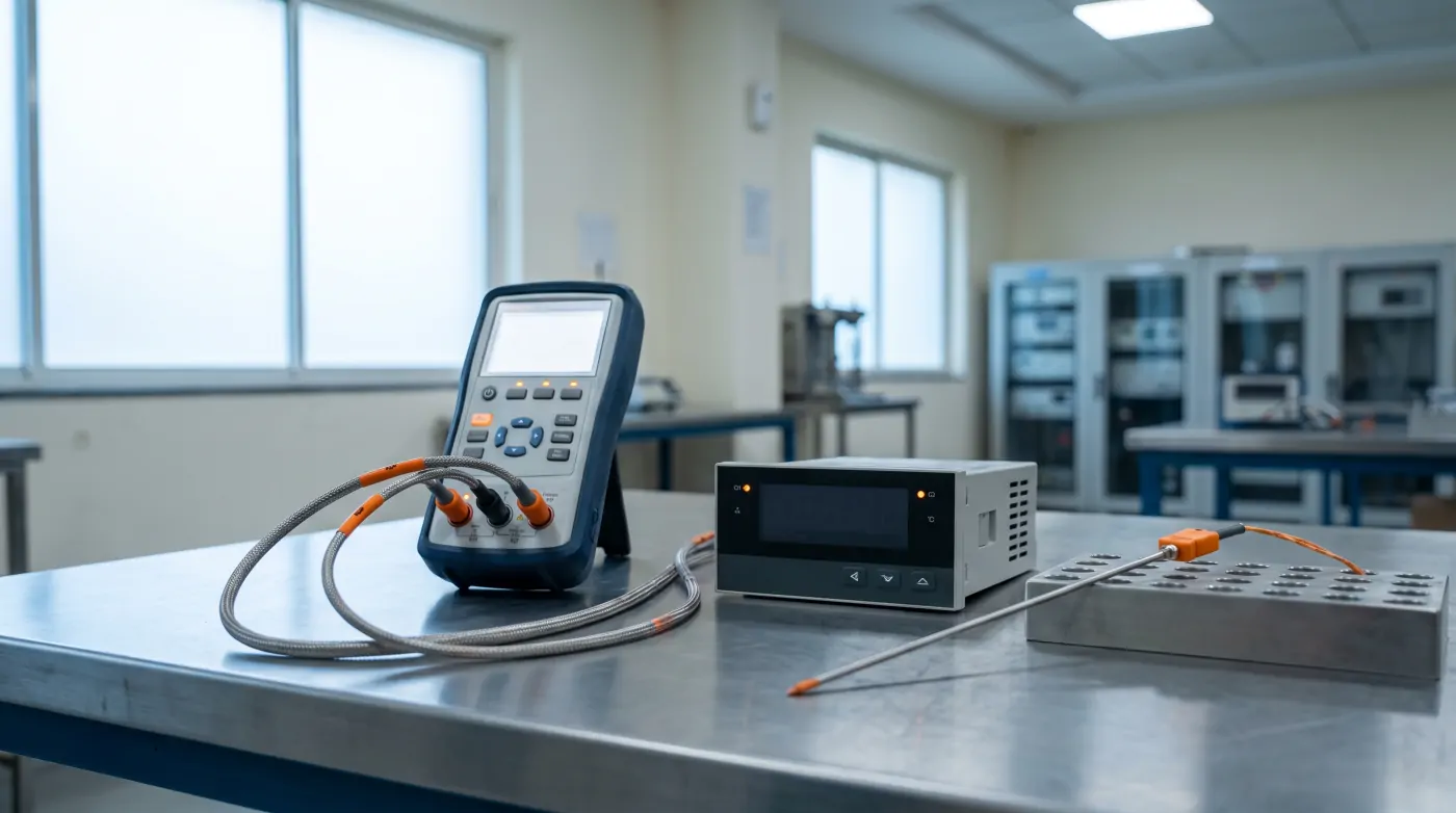
- Reference temperature source: Dry-block calibrator (Fluke, AMETEK Jofra, or equivalent) with accuracy better than ±0.1°C at the range of interest, OR a liquid bath calibrator for immersion sensors
- Reference thermometer / SPRT: Secondary Reference Platinum Resistance Thermometer (SPRT) with calibration traceable to NABL/NPL, accuracy ±0.05°C
- Decade resistance box or millivolt source: For direct injection calibration of the temperature controller input without a physical temperature source
- 4.5-digit or better digital multimeter: For millivolt measurement of thermocouple outputs
- Calibration record sheets and certificates
Never calibrate temperature instruments against an uncalibrated reference — all reference standards must have a current calibration certificate traceable to national standards (NABL in India, NPL for primary standards).
Understanding Thermocouple Types and Signals
Indian industrial plants predominantly use K-type thermocouples (chromel-alumel) for general process temperatures up to 1200°C, J-type (iron-constantan) for lower temperatures up to 750°C, and PT100 (platinum resistance thermometer, Class A) for precision temperature measurement in pharmaceutical, food, and HVAC applications.
Thermocouple outputs in millivolts at common temperatures (referenced to 0°C cold junction):
- K-type at 100°C: 4.096 mV
- K-type at 200°C: 8.138 mV
- K-type at 500°C: 20.644 mV
PT100 resistance at common temperatures:
- 0°C: 100.00 Ω
- 100°C: 138.51 Ω
- 200°C: 175.86 Ω
Knowing these values allows you to verify the sensor electrically without needing a temperature reference during preliminary checks.
Step 1: Sensor Verification
Before calibrating the controller, verify the sensor is functioning correctly:
Disconnect the thermocouple from the controller. Measure the resistance across the thermocouple leads with a multimeter. For K-type thermocouples, typical room temperature resistance is 2–20 Ω depending on lead length. Very high resistance (>1000 Ω) or open circuit indicates a broken thermocouple. Near-zero resistance indicates a short.
For PT100, measure resistance at room temperature. Compare against the PT100 table — at 25°C, PT100 should read approximately 109.73 Ω. Deviation of more than ±1 Ω warrants replacement.
Visually inspect the thermocouple for discolouration, pitting, or physical damage at the tip. Sheaths contaminated by the process material can cause drift even if the electrical resistance appears normal.
Step 2: Cold Junction Compensation Check
Thermocouples measure temperature relative to a cold junction (the point where thermocouple wire connects to copper wire or instrument terminals). The temperature controller applies a cold junction compensation (CJC) correction based on the terminal block temperature measured by an internal sensor.
To verify CJC accuracy: measure the terminal block temperature with a reference thermometer. Compare it to the CJC value reported by the controller (this is accessible in some controllers' diagnostic screens or can be inferred from the displayed process value when a 0 mV input is applied).
A faulty or miscalibrated CJC sensor causes a constant offset error equal to the CJC measurement error. This is a common but overlooked source of temperature error in hot environments.
Step 3: Inject Reference Signals and Record Errors
Using a millivolt source (for thermocouple inputs) or decade resistance box (for PT100/RTD inputs), inject reference signals corresponding to at least 5 calibration points across the measurement range:
- Typical calibration points: 0%, 25%, 50%, 75%, 100% of measurement range
- For a 0–500°C K-type application: test at 0°C (0 mV), 125°C (5.071 mV), 250°C (10.153 mV), 375°C (15.301 mV), 500°C (20.644 mV)
At each calibration point, record:
- Injected reference signal (mV or Ω)
- Controller displayed value (°C)
- Error = Displayed value − Expected value
Plot the errors to identify if there is a zero error (constant offset), span error (increasing error with temperature), or non-linearity.
Step 4: PID Auto-Tuning and Manual PID Tuning
PID tuning is distinct from calibration but is often performed at the same time during commissioning or maintenance. PID tuning ensures the temperature controller responds correctly to setpoint changes and disturbances.
Auto-tune: Most modern temperature controllers (Autonics, Yokogawa, Omron, Fuji, PID48/72 series) have a built-in auto-tune function. With the process at ambient temperature and the setpoint at a representative operating point, activate auto-tune. The controller will induce a step response, measure the process characteristics (dead time, time constant, gain), and calculate P, I, and D parameters using the Ziegler-Nichols or Cohen-Coon method internally.
Manual PID tuning for precise applications:
- Start with I and D set to 0 (P-only mode)
- Increase P gain until the response oscillates at the setpoint with constant amplitude (ultimate gain)
- Record ultimate gain (Ku) and oscillation period (Tu)
- Apply Ziegler-Nichols closed-loop tuning rules: Kp = 0.6×Ku, Ti = Tu/2, Td = Tu/8
For processes with large dead times (slow furnace heating, thick-walled heat exchangers), IMC (Internal Model Control) tuning is more stable than Ziegler-Nichols.
Step 5: Document and Issue Calibration Certificate
Record all calibration results on a calibration certificate that includes:
- Instrument tag number and description
- Calibration date and next due date
- Reference standard used and its certificate number
- As-found readings (before any adjustment)
- Adjustments made (zero and span trim, if applicable)
- As-left readings (after adjustment)
- Acceptance criteria and pass/fail status
- Technician name and signature
Keep calibration records for the lifetime of the instrument plus 3 years for ISO 9001 compliance. For instruments in pharmaceutical GMP environments, 21 CFR Part 11 requires electronic records to be immutable and traceable.
Common Calibration Errors to Avoid
- Calibrating the controller alone without verifying the sensor — the system accuracy includes both controller and sensor
- Using thermocouple extension wire of the wrong alloy for lead runs — K-type thermocouple requires K-type extension wire; using copper wire introduces junction EMFs that create fixed-offset errors
- Ignoring the effect of electrical interference on thermocouple signals — shield all thermocouple cables and verify the shield is earthed at one end only